Extension - Arduino
Introduction
The Arduino library is written in C++ and communicates with the K210 AI Vision Sensor via the I²C interface.
Based on this library, users can develop programs that achieve higher efficiency and richer functionalities. This tutorial mainly introduces usage through the Wire I²C library, but it is not limited to Wire. You may also refer to the override example to implement usage in other environments.
Quick Start
Hardware Requirements
|
|
|---|---|
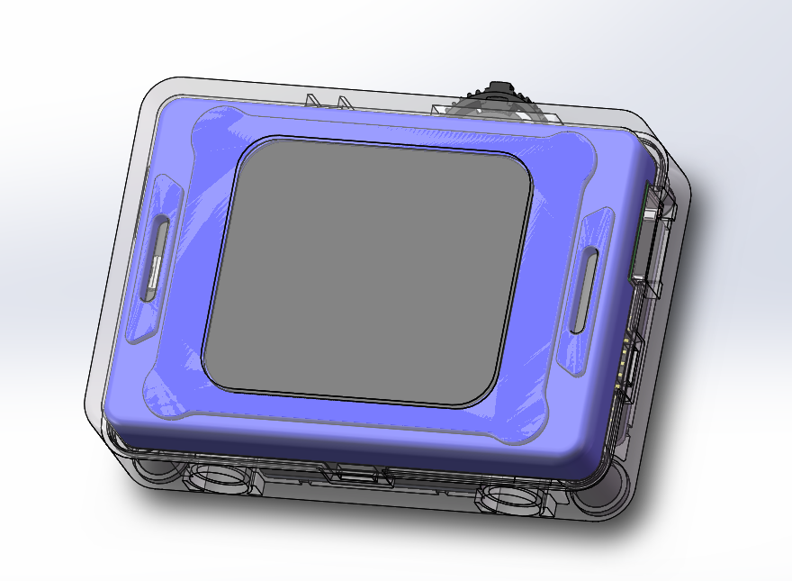
K210 AI Vision Sensor |
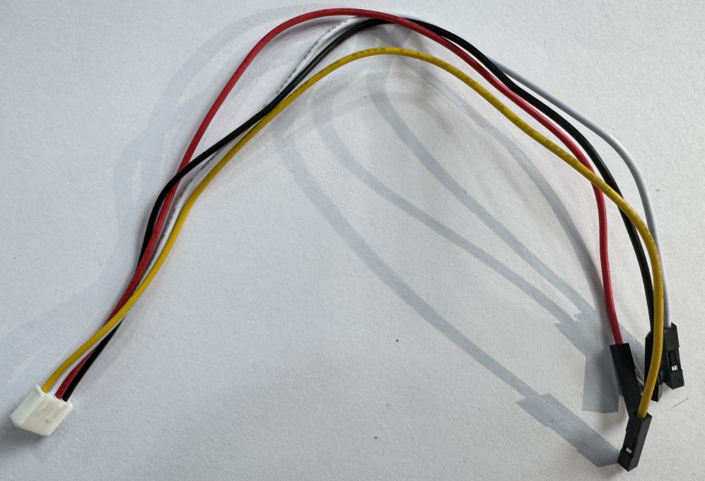
Grove to 4-pin Dupont cable |
|
|
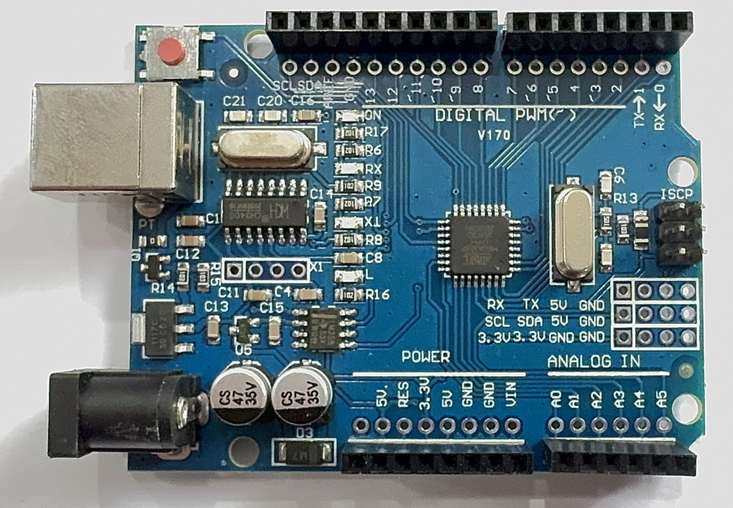
Arduino Uno |
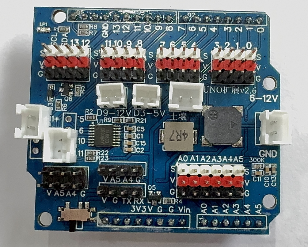
Expansion Shield |
Software Requirements
|
|
|---|---|
Arduino IDE |
Vision Module API Library |

Refer to the Grove port pin definitions for correct wiring.
Library Acquisition
You can download the required API library for the vision module from:
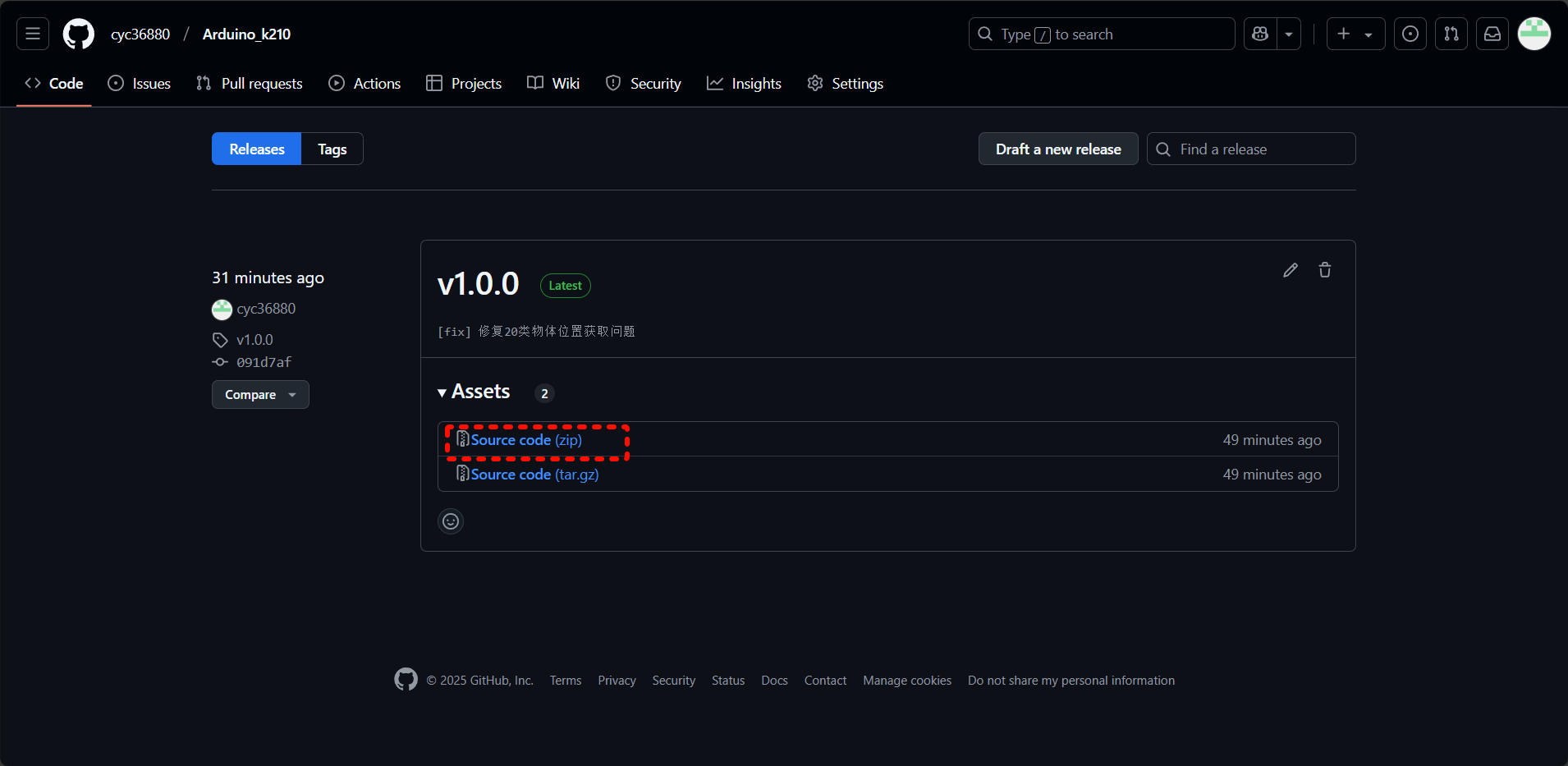
GitHub:
Visit GitHub
Navigate to the Releases section on the lower right.
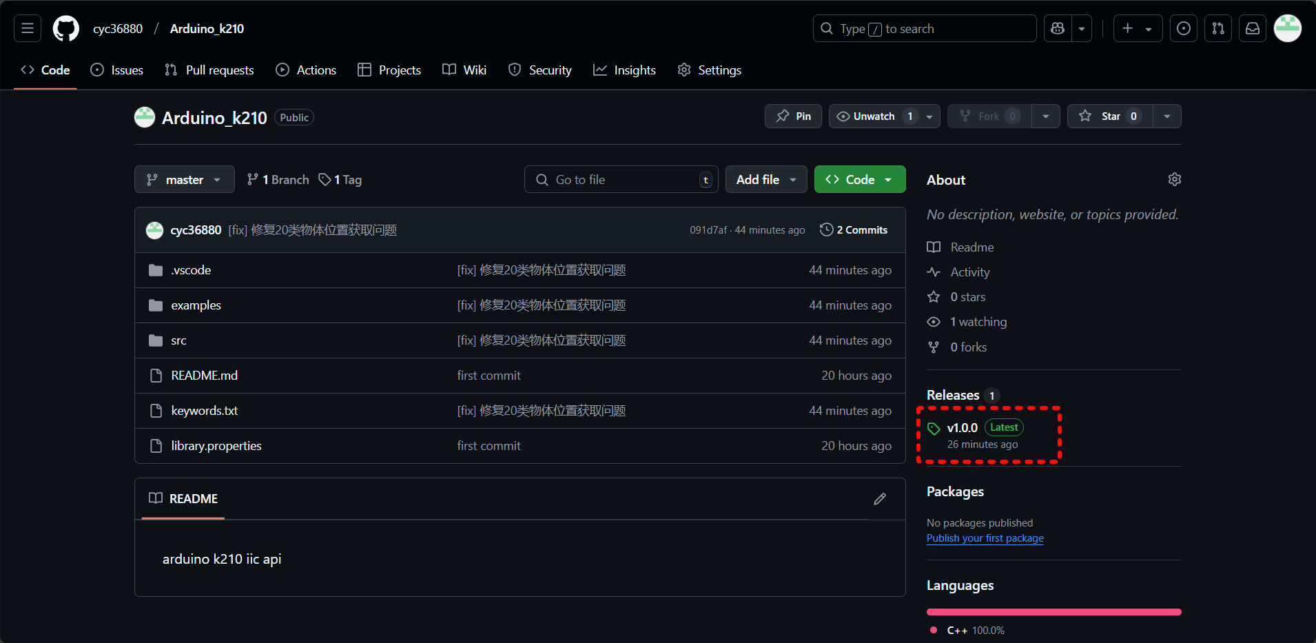
Download the latest packaged version.
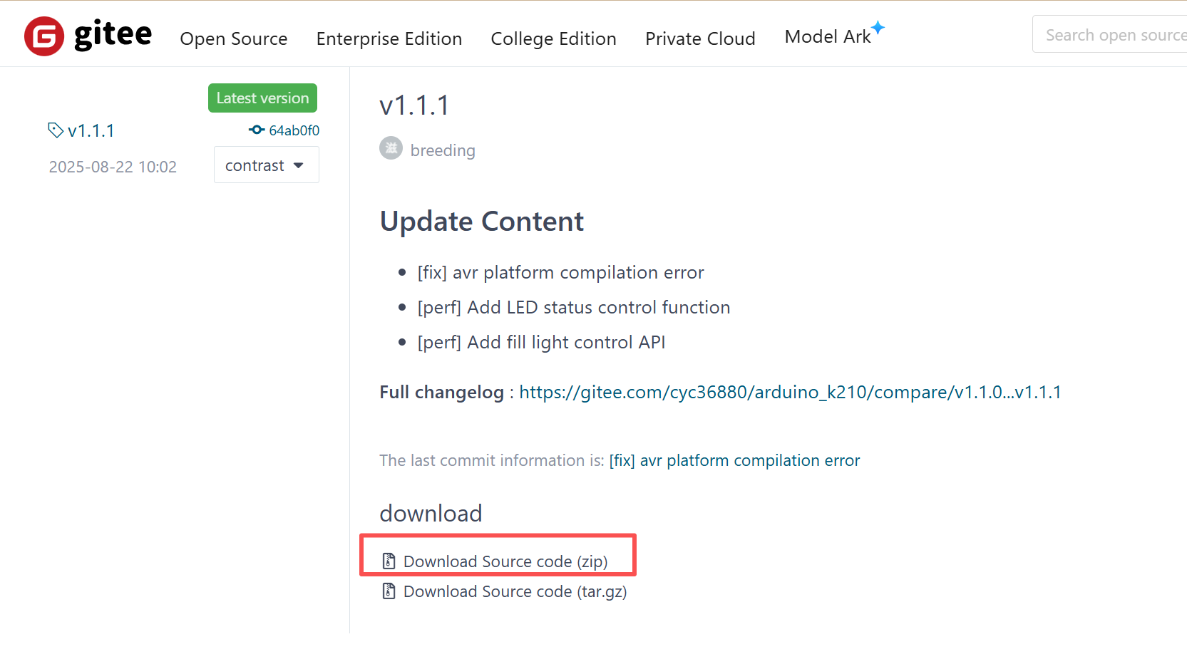
Gitee:
1.Visit Gitee
2. Navigate to the Releases section on the lower right.
Download the latest packaged version.
Importing the Library in Arduino IDE
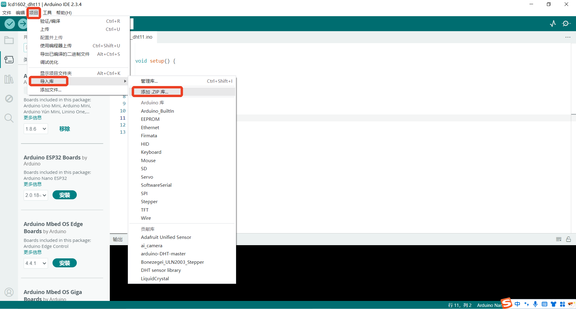
Step 1: Open the Arduino IDE, create a new project, go to the Sketch menu, select Include Library → Add .ZIP Library…
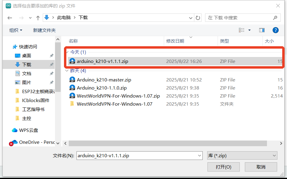
Step 2: Locate the downloaded library file (make sure you have the correct version), select it, and click Open in the bottom-right corner.
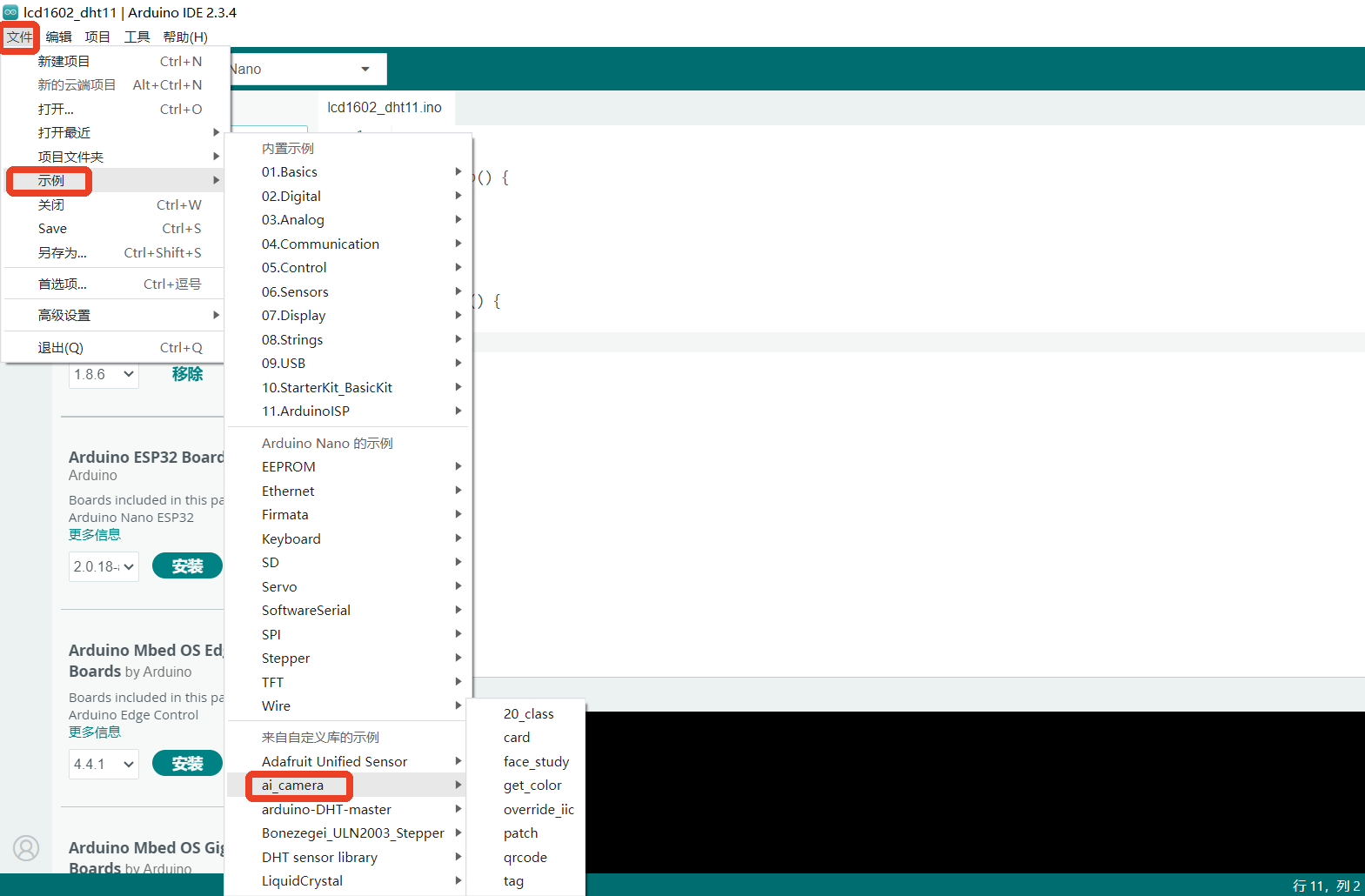
Step 3: In the File menu, navigate to Examples. At the bottom under Examples from Custom Libraries, if you see ai_camera, the library has been successfully imported.
Examples
The ai_cameralibrary provides multiple sample sketches with detailed comments. Together with the API documentation, these examples help you quickly learn how to use the library.
Below is how to open and compile an example to verify your build environment. If the sketch compiles successfully, your environment is set up correctly.
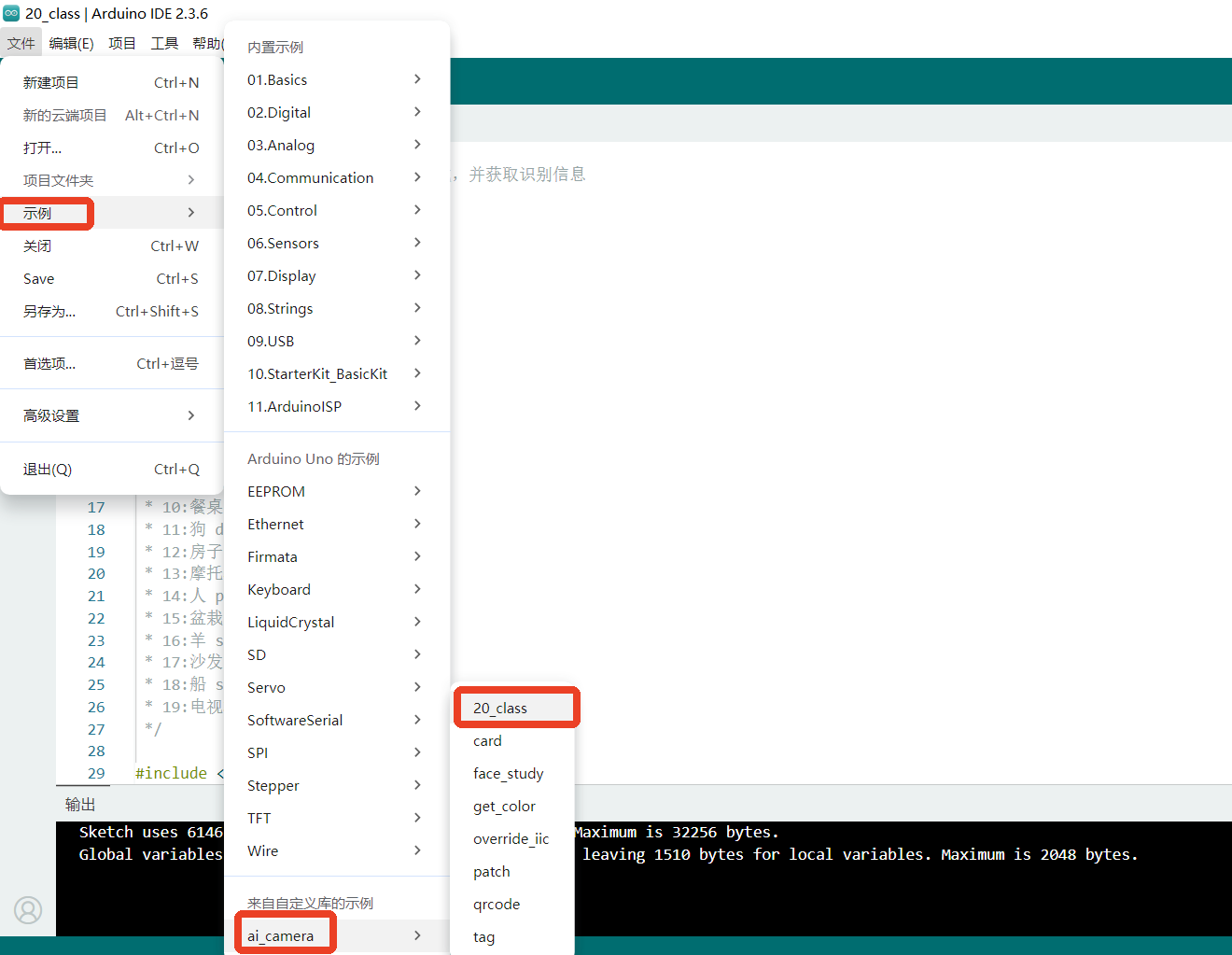
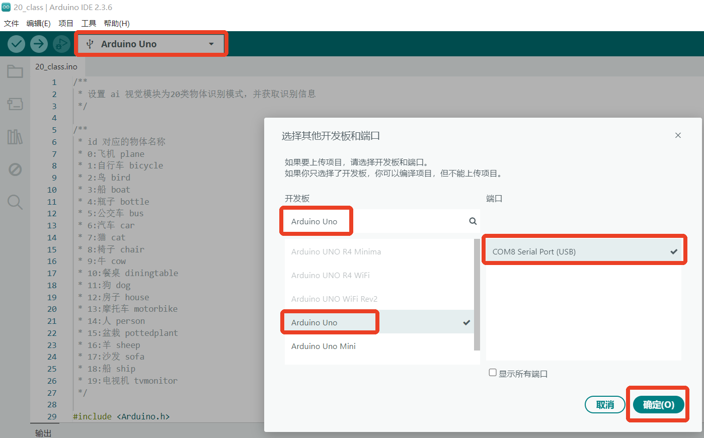
Step 1: The following walkthrough uses 20-Class Object Recognition as the example.
Step 2: Select the development board and the corresponding COM port currently in use, then click OK.
Step 3: Click the Verify/Compile button in the upper-left corner. Wait for the compilation to finish. If successful, the output window will display messages as shown in the highlighted box.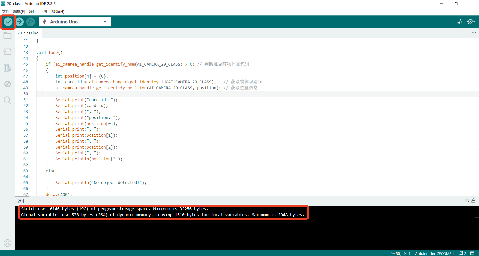
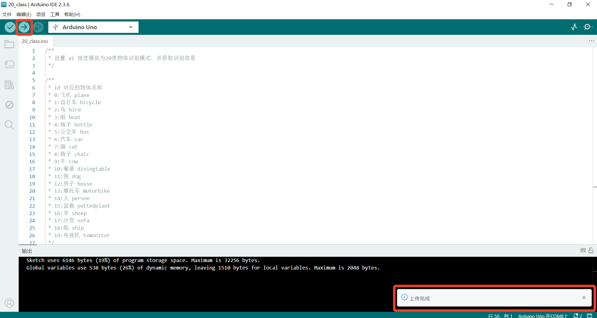
Step 4: Click the Upload button in the upper-left corner. The IDE will first compile, then automatically upload the code to the board. Once uploading is complete, a confirmation message will appear in a popup window as shown in the highlighted box.
Step 5: Demo Effect
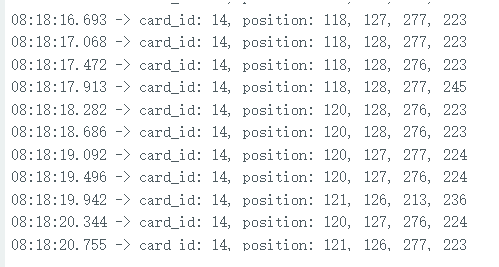
The K210 Vision Sensor will recognize objects and label them with their names and position information.
Additionally, print the object name and position information to the serial monitor.
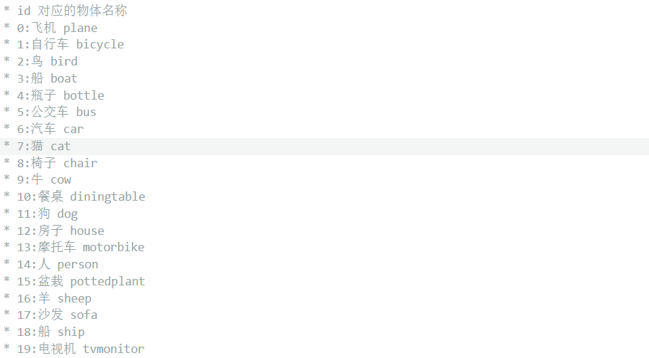
card_id maps to the object names (see the figure on the right).
position contains the bounding box: X, Y, W, H.

API
The API is used to operate the Vision Module. Communication with the module follows a specified protocol and requires basic data handling. By using the API, you can abstract away low-level operations and simplify your application logic.
(The examples below take an ESP32 development board as the target platform.)
Usage Notes
AprilTag generation (Tag Recognition)
You can generate tags using an online AprilTag generator.
Set Tag Family toTAG36H11 (this is the family used by the Vision Module).
Set Tag ID as needed (typical range: 0–200).
Print the generated tag and ensure good lighting and focus during testing.
QR code generation (QR Code Recognition)
Use any standard QR code generator website or tool.
Enter the text/content to be encoded and click Generate.
Ensure sufficient print quality and size so the module can decode reliably.
Class: AiCamera
The AiCamera class is the fundamental object used to operate the AI Vision Module.
Constructor
class AiCamera(uint8_t addr=0x24)
Creates an AiCamera object.
Parameters:
addr→ The I²C address of the Vision Module.
Default value: 0x24
Since the AI Vision Module typically uses a single address, the default setting is usually sufficient.
Parameter Macros
enum Register
{
    AI_CAMERA_COLOR,            // 颜色获取
    AI_CAMERA_PATCH,            // 色块追踪
    AI_CAMERA_TAG,              // 标签识别
    AI_CAMERA_LINE,             // 线条识别
    AI_CAMERA_20_CLASS,         // 20类物体识别
    AI_CAMERA_QRCODE,           // 二维码识别
    AI_CAMERA_FACE_ATTRIBUTE,   // 人脸属性
    AI_CAMERA_FACE_RE,          // 人脸识别
    AI_CAMERA_DEEP_LEARN,       // 深度学习
    AI_CAMERA_CARD,             // 卡片识别
    AI_CAMERA_WIFI_SERVER,      // 无线图传
};
enum Color
{
    AI_CAMERA_COLOR_RED,     // 红色
    AI_CAMERA_COLOR_GREEN,   // 绿色
    AI_CAMERA_COLOR_BLUE,    // 蓝色
    AI_CAMERA_COLOR_YELLOW,  // 黄色
    AI_CAMERA_COLOR_BLACK,   // 黑色
    AI_CAMERA_COLOR_WHITE,   // 白色
};
These macros are used when switching modes, reading/writing data in a specific mode, and configuring color settings of the Vision Module.
Function
Init
Init(int sda=-1, int scl=-1)
Description:
Initializes the AI Vision Module over the I²C interface.
Parameters:
sda → I²C data line (SDA).
Default: -1 (use the board’s default SDA pin).
scl → I²C clock line (SCL).
Default: -1 (use the board’s default SCL pin).
Example:
#include <Arduino.h>   // 引入 Arduino 头文件
#include "ai_camera.h" // 引入 ai视觉模块的库头文件

// 设置 ai 视觉模块操作句柄
AiCamera ai_camrea_handle;


void setup()
{
    ai_camrea_handle.Init();   // 初始化
}

void loop()
{
}
begin
begin(int sda=-1, int scl=-1)
Use the same style as Init to define this function, in order to keep it consistent with the Arduino coding style.
set_sys_mode
set_sys_mode(uint8_t mode);
Set the working mode of the AI visual module.
Parameter :
mode – Operating Mode
Refer to Parameter Macros.
Example:
#include <Arduino.h>   // 引入 Arduino 头文件
#include "ai_camera.h" // 引入 ai视觉模块的库头文件

// 设置 ai 视觉模块操作句柄
AiCamera ai_camrea_handle;


void setup()
{
    ai_camrea_handle.Init();   // 初始化
    // 设置模式为二维码识别模式
    ai_camrea_handle.set_sys_mode(AI_CAMERA_QRCODE);
}

void loop()
{
}
After uploading the code to the development board and resetting the chip, the Vision Module’s operating mode switched from Line Recognition mode to QR Code Recognition mode.
get_sys_mode
get_sys_mode()
Get the current operating mode of the device
Return Value:
AI_CAMERA_COLOR ~ AI_CAMERA_CARD
Indicates the current mode type. Compare the return value with the Parameter Macros to determine the mode.
Example:
#include <Arduino.h>   // 引入 Arduino 头文件
#include "ai_camera.h" // 引入 ai视觉模块的库头文件

// 设置 ai 视觉模块操作句柄
AiCamera ai_camrea_handle;


void setup()
{
    Serial.begin(115200);      // 初始化串口
    ai_camrea_handle.Init();   // 初始化
}

void loop()
{
    int get_mode = ai_camrea_handle.get_sys_mode(); // 获取系统模式
    if (get_mode == AI_CAMERA_TAG)
    {
        Serial.println("处于标签识别模式");
    }
    else if (get_mode == AI_CAMERA_FACE_ATTRIBUTE)
    {
        Serial.println("处于人脸检测模式");
    }
    else
    {
        Serial.println("其它模式");
    }
    delay(400);
}
When switching modes using the rotary dial, if you switch to Tag Recognition mode or Face Detection mode, the serial monitor will print the corresponding mode name.
get_color_rgb
get_color_rgb(int rgb[3])
Retrieves the RGB values from the Color Recognition mode.
Parameters:
rgb[3] → An integer array of size 3, used as the RGB buffer.
Example:
#include <Arduino.h>   // 引入 Arduino 头文件
#include "ai_camera.h" // 引入 ai视觉模块的库头文件

// 设置 ai 视觉模块操作句柄
AiCamera ai_camrea_handle;


void setup()
{
    Serial.begin(115200);      // 初始化串口
    ai_camrea_handle.Init();   // 初始化
    // 切换模式到颜色获取模式
    ai_camrea_handle.set_sys_mode(AI_CAMERA_COLOR);
    delay(1000);                    // 等待切换完成
}

void loop()
{
    int rgb[3] = {0}; // rgb数组数据缓冲区
    ai_camrea_handle.get_color_rgb(rgb); // 获取rgb数据
    Serial.print("rgb:(");
    Serial.print(rgb[0]);
    Serial.print(" ");
    Serial.print(rgb[1]);
    Serial.print(" ");
    Serial.print(rgb[2]);
    Serial.println(")");

    delay(400);
}
In the center of the visual module is a white rectangular box, which is used for color extraction.
Below the white box, the screen displays the extracted RGB value in real time, which is consistent with the result of serial port printing output.
get_color_rgb
get_color_rgb(int &r, int &g, int &b)
Parameters:
r → Reference to an integer storing the Red value
g → Reference to an integer storing the Green value
b → Reference to an integer storing the Blue value
** Example:**
#include <Arduino.h>   // 引入 Arduino 头文件
#include "ai_camera.h" // 引入 ai视觉模块的库头文件

// 设置 ai 视觉模块操作句柄
AiCamera ai_camrea_handle;


void setup()
{
    Serial.begin(115200);      // 初始化串口
    ai_camrea_handle.Init();   // 初始化
    // 切换模式到颜色获取模式
    ai_camrea_handle.set_sys_mode(AI_CAMERA_COLOR);
    delay(1000);                    // 等待切换完成
}

void loop()
{
    int r, g, b; //
    ai_camrea_handle.get_color_rgb(r, g, b); // 获取rgb数据
    Serial.print("rgb:(");
    Serial.print(r);
    Serial.print(" ");
    Serial.print(g);
    Serial.print(" ");
    Serial.print(b);
    Serial.println(")");

    delay(400);
}
Use the reference to the previous function of the same name
set_find_color
set_find_color(uint8_t color_id)
Sets the target color for Color Block Tracking mode.
Parameters:
color_id →The color to be tracked. Options:
AI_CAMERA_COLOR_RED // Red
AI_CAMERA_COLOR_GREEN // Green
AI_CAMERA_COLOR_BLUE // Blue
AI_CAMERA_COLOR_YELLOW // Yellow
AI_CAMERA_COLOR_BLACK // Black
AI_CAMERA_COLOR_WHITE // White
** Example:**
#include <Arduino.h>   // 引入 Arduino 头文件
#include "ai_camera.h" // 引入 ai视觉模块的库头文件

// 设置 ai 视觉模块操作句柄
AiCamera ai_camrea_handle;


void setup()
{
    Serial.begin(115200);      // 初始化串口
    ai_camrea_handle.Init();   // 初始化
    // 切换模式到色块追踪模式
    ai_camrea_handle.set_sys_mode(AI_CAMERA_PATCH);
    delay(1000);                    // 等待切换完成
    ai_camrea_handle.set_find_color(AI_CAMERA_COLOR_GREEN);// 设置追踪绿色
}

void loop()
{
}
After uploading the code to the development board and resetting the chip, the Vision Module switches from Color Recognition mode to Color Block Tracking mode, and the top-right indicator updates to show the tracking color as Green.
face_study
face_study()
Trigger Face Recognition Learning
It learns only when a face is recognized, otherwise the instruction is invalid
After learning, the ID of the current face is automatically assigned, ranging from 0 to 3. If more than 4 are exceeded, it will be overwritten from 0
Example:
#include <Arduino.h>   // 引入 Arduino 头文件
#include "ai_camera.h" // 引入 ai视觉模块的库头文件

// 设置 ai 视觉模块操作句柄
AiCamera ai_camrea_handle;

void setup()
{
    Serial.begin(115200);      // 初始化串口
    ai_camrea_handle.Init();   // 初始化
    // 切换模式到人脸识别模式
    ai_camrea_handle.set_sys_mode(AI_CAMERA_FACE_RE);
    delay(1000);                    // 等待切换完成
    ai_camrea_handle.face_study();  // 人脸学习
}

void loop()
{
}
Upload the code to the development board, and reset the chip when the visual module can recognize the face. The visual module switches from color recognition mode to face recognition mode and learns the recognized face. The white box of the face is switched to orange box, and an ID is assigned to it.
deep_learn_study
deep_learn_study()
Make deep recognition learning
Take a series of photos when the photo is longer than 5s or the category exceeds 4, and enter recognition mode
Example:
#include <Arduino.h>   // 引入 Arduino 头文件
#include "ai_camera.h" // 引入 ai视觉模块的库头文件

// 设置 ai 视觉模块操作句柄
AiCamera ai_camrea_handle;


void setup()
{
    Serial.begin(115200);      // 初始化串口
    ai_camrea_handle.Init();   // 初始化
    // 切换模式到深度识别模式
    ai_camrea_handle.set_sys_mode(AI_CAMERA_DEEP_LEARN);
    delay(1000);                          // 等待切换完成
    ai_camrea_handle.deep_learn_study();  // 深度学习
}

void loop()
{
}
Upload the code to the development board, reset the chip, and switch the vision module to deep learning mode and carry out deep learning.
get_face_attributes
get_face_attributes(int &is_male, int &is_mouth_open, int &is_smail, int &is_glasses, uint8_t index=0)
Obtain face attributes
Parameters:
is_male → Whether the face is male
is_mouth_open → Whether the mouth is open
is_glasses → Whether glasses are worn
index → The index of the detected face (default: the first face)
Example:
#include <Arduino.h>    // 引入 Arduino 头文件
#include "ai_camera.h"  // 引入 ai视觉模块的库头文件

// 设置 ai 视觉模块操作句柄
AiCamera ai_camrea_handle;

void setup()
{
    Serial.begin(115200); // 初始化串口
    ai_camrea_handle.begin();    // 初始化
    ai_camrea_handle.set_sys_mode(AI_CAMERA_FACE_ATTRIBUTE); // 设置模式为人脸属性识别模式
    delay(1000); // 等待切换完成
}

void loop()
{
    // 判断是否找到人脸
    if (ai_camrea_handle.get_identify_num(AI_CAMERA_FACE_ATTRIBUTE) > 0)
    {
        // 获取人脸属性
        int is_male, is_mouth_open, is_smail, is_glasses;
        ai_camrea_handle.get_face_attributes(is_male, is_mouth_open, is_smail, is_glasses);
        Serial.print("is_male: ");
        Serial.print(is_male);
        Serial.print(", is_mouth_open: ");
        Serial.print(is_mouth_open);
        Serial.print(", is_smail: ");
        Serial.print(is_smail);
        Serial.print(", is_glasses: ");
        Serial.println(is_glasses);
    }
    else
    {
        Serial.println("No face detected.");
    }

    delay(400);
}
get_identify_num
get_identify_num(uint8_t features, uint8_t total=0)
Get the number of identifications or whether the identification was made
**Parameters: **
features → Feature selection
AI_CAMERA_PATCH # Color Block Tracking
AI_CAMERA_TAG # Tag Recognition
AI_CAMERA_LINE # Line Recognition
AI_CAMERA_20_CLASS# 20-Class Object Recognition
AI_CAMERA_QRCODE # QR Code Recognition
AI_CAMERA_FACE_ATTRIBUTE # Face Attribute Recognition
AI_CAMERA_FACE_RE # Face Recognition
AI_CAMERA_DEEP_LEARN # Deep Learning
AI_CAMERA_CARD # Card Recognition
total → Total number of recognized objects
In Face Recognition mode:
total = 0 (default) → Returns the number of learned faces detected.
total = 1 → Returns the total number of faces detected on screen (both learned and unlearned).
In other modes: This parameter is ignored.
Return Value:
In Color Block Tracking, Line Recognition, QR Code Recognition, and Deep Learning modes:
Returns 1 if an object is recognized.
Returns 0 if no object is recognized.
In Tag Recognition, 20-Class Object Recognition, Face Attribute, and Card Recognition modes:
Returns the number of objects recognized.
In Face Recognition mode:
Default returns the number of learned faces recognized.
If total = 1, returns the total number of faces (learned + unlearned).
Example:
#include <Arduino.h>   // 引入 Arduino 头文件
#include "ai_camera.h" // 引入 ai视觉模块的库头文件

// 设置 ai 视觉模块操作句柄
AiCamera ai_camrea_handle;


void setup()
{
    Serial.begin(115200);      // 初始化串口
    ai_camrea_handle.Init();   // 初始化
    // 切换模式到色块追踪模式
    ai_camrea_handle.set_sys_mode(AI_CAMERA_PATCH);
    delay(1000);                          // 等待切换完成
    ai_camrea_handle.set_find_color(AI_CAMERA_COLOR_GREEN);// 设置追踪绿色
}

void loop()
{
    // 判断是否找到色块
    if (ai_camrea_handle.get_identify_num(AI_CAMERA_PATCH) > 0)
    {
        Serial.println("find patch");
    }
    else
    {
        Serial.println("no find patch");
    }
    delay(400);
}
When the visual module recognizes a green object, it boxes it out and prints “find patch” on the serial port. If no green object is recognized, it prints “no find patch” on the serial port.
get_qrcode_content
get_qrcode_content()
Get the content identified by the QR code
Return Value:
Returns a string (std::string type).
Example:

A QR code with the content “hello”.
#include <Arduino.h>   // 引入 Arduino 头文件
#include "ai_camera.h" // 引入 ai视觉模块的库头文件

// 设置 ai 视觉模块操作句柄
AiCamera ai_camrea_handle;

void setup()
{
    Serial.begin(115200);      // 初始化串口
    ai_camrea_handle.Init();   // 初始化
    // 切换模式到二维码识别模式
    ai_camrea_handle.set_sys_mode(AI_CAMERA_QRCODE);
    delay(1000);              // 等待切换完成
}

void loop()
{
    // 判读是否找到二维码
    if (ai_camrea_handle.get_identify_num(AI_CAMERA_QRCODE) > 0)
    {
        // 获取二维码内容
        std::string qrcode_content = ai_camrea_handle.get_qrcode_content();
        Serial.print("qrocde content: ");
        Serial.println(qrcode_content);
    }
    else
    {
        Serial.println("no find qrcode");
    }
    delay(400);
}
When the visual module recognizes the QR code generated by the QR code generation tool with the content “hello”, it prints “qrcode content: hello” through the serial port. If the QR code is not recognized, it prints “no find qrcode” through the serial port.
get_identify_id
get_identify_id(uint8_t features, uint8_t index=0)
Get the ID of the object being recognized
Interpretation of id in Different Modes
Color Block Tracking
id = 1 ~ 6, representing Red, Green, Blue, Yellow, Black, White.
You can use the color macros defined in class AiCamera to judge.
(Note: this value reflects the set color id, regardless of whether the block is detected.)
Tag Recognition
id = 0 ~ …, corresponds to the tag ID defined when generating the AprilTag
20-Class Object Recognition
id = 0 ~ 19, representing:
“airplane”, “bicycle”, “bird”, “boat”, “bottle”, “bus”, “car”, “cat”, “chair”, “cow”, “dining table”, “dog”, “house”, “motorbike”, “person”, “potted plant”, “sheep”, “sofa”, “train”, “tv monitor”.
Face Recognition / Deep Learning
id = 0 ~ 3, automatically assigned in order when learning.
Card Recognition
id = 0 ~ 6, representing:
Green Light, Left Turn, Stop, Red Light, Right Turn, Horn, Target.
Parameters:
features — Function selection
AI_CAMERA_PATCH — Color Block Tracking (single)
AI_CAMERA_TAG — Tag Recognition (single)
AI_CAMERA_20_CLASS — 20-Class Object Recognition (multi)
AI_CAMERA_FACE_RE — Face Recognition (multi)
AI_CAMERA_DEEP_LEARN — Deep Learning (single)
AI_CAMERA_CARD — Card Recognition (multi)
index — Index of the recognized object
Range: 0 ~ 3
Only meaningful in multi-object recognition modes (20-Class, Face, Card).
Return Value:
id of the recognized object.
Meaning depends on the selected mode (see explanation above).
Example 1: Judge the Recognized Tag ID
|
|
|
|---|---|---|
|
|
|
|
|
|
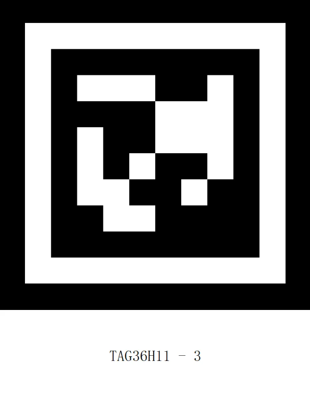
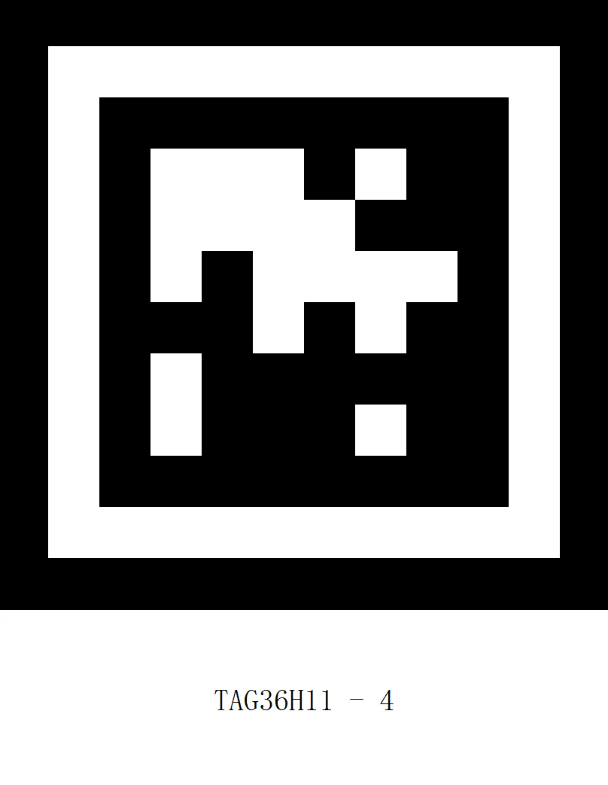

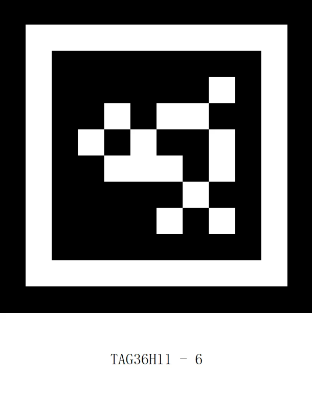

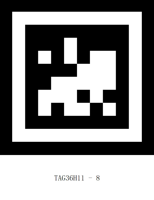
ID tags from 0 to 8.
#include <Arduino.h>   // 引入 Arduino 头文件
#include "ai_camera.h" // 引入 ai视觉模块的库头文件

// 设置 ai 视觉模块操作句柄
AiCamera ai_camrea_handle;

void setup()
{
    Serial.begin(115200);      // 初始化串口
    ai_camrea_handle.Init();   // 初始化
    // 切换模式到标签识别模式
    ai_camrea_handle.set_sys_mode(AI_CAMERA_TAG);
    delay(1000);               // 等待切换完成
}

void loop()
{
    // 判读是否找到标签
    if (ai_camrea_handle.get_identify_num(AI_CAMERA_TAG) > 0)
    {
        // 获取标签id
        int target_id = ai_camrea_handle.get_identify_id(AI_CAMERA_TAG);
        Serial.print("tag id: ");
        Serial.println(target_id);
    }
    else
    {
        Serial.println("no find tag");
    }
    delay(400);
}
When the visual module does not recognize the tag, it prints “no find tag” on the serial port. When the tag is recognized, it prints the ID of the tag.
Example 2: Judge Recognized 20-Class Objects
|
|
|---|---|


“Bike” and “car” pictures.
#include <Arduino.h>   // 引入 Arduino 头文件
#include "ai_camera.h" // 引入 ai视觉模块的库头文件

// 设置 ai 视觉模块操作句柄
AiCamera ai_camrea_handle;


void setup()
{
    Serial.begin(115200);      // 初始化串口
    ai_camrea_handle.Init();   // 初始化
    // 切换模式到20类物体识别模式
    ai_camrea_handle.set_sys_mode(AI_CAMERA_20_CLASS);
    delay(1000);               // 等待切换完成
}

void loop()
{
    // 判读是否找到20类物体
    if (ai_camrea_handle.get_identify_num(AI_CAMERA_20_CLASS) > 0)
    {
        // 获取20类物体id
        uint8_t target_id = ai_camrea_handle.get_identify_id(AI_CAMERA_20_CLASS);
        if (target_id == 1)
        {
            Serial.println("识别到自行车");
        }
        else
        {
            Serial.println("其他物体");
        }
    }
    else
    {
        Serial.println("no find 20 class");
    }
    delay(400);
}
When the vision module recognizes “bicycle”, it prints “recognized bicycle” on the serial port; when the vision module recognizes “car”, it prints “other objects” on the serial port; when no objects matching the 20 categories are recognized, it prints “no find 20 class”.
get_identify_rotation
get_identify_rotation(uint8_t features, uint8_t index=0)
Get the rotation Angle of the object being identified
Currently, only the tag recognition mode supports the rotation Angle. The value obtained by other modes is always 0
**Parameter **
features function selection
AI_CAMERA_TAG # Tag Recognition
index: which object the index identifies
The default is 0. Generally, 0 is ok. This parameter is reserved for future functional extensions
Return Value:
0~359
Example:
#include <Arduino.h>   // 引入 Arduino 头文件
#include "ai_camera.h" // 引入 ai视觉模块的库头文件

// 设置 ai 视觉模块操作句柄
AiCamera ai_camrea_handle;

void setup()
{
    Serial.begin(115200);      // 初始化串口
    ai_camrea_handle.Init();   // 初始化
    // 切换模式到标签识别模式
    ai_camrea_handle.set_sys_mode(AI_CAMERA_TAG);
    delay(1000);               // 等待切换完成
}

void loop()
{
    // 判读是否找到标签
    if (ai_camrea_handle.get_identify_num(AI_CAMERA_TAG) > 0)
    {
        // 获取标签旋转角度
        int rot = ai_camrea_handle.get_identify_rotation(AI_CAMERA_TAG);
        Serial.print("rot: ");
        Serial.println(rot);
    }
    else
    {
        Serial.println("no find tag");
    }
    delay(400);
}
When the visual module recognizes the tag, rotate the visual module and print the Angle of the tag relative to the visual module through the serial port. If the tag is not recognized, print “no find tag” through the serial port.
get_identify_position
get_identify_position(uint8_t features, int16_t position[4], uint8_t index=0)
Get the position of the object being identified
Line recognition : There are three rectangular boxes, from bottom to top, index 0,1,2
Parameter:
features → Feature selection
AI_CAMERA_PATCH // Color Block Tracking
AI_CAMERA_TAG // Tag Recognition
AI_CAMERA_LINE // Line Recognition
AI_CAMERA_20_CLASS // 20-Class Object Recognition
AI_CAMERA_QRCODE // QR Code Recognition
AI_CAMERA_FACE_ATTRIBUTE // Face Attribute Recognition
AI_CAMERA_FACE_RE //Face Recognition
AI_CAMERA_DEEP_LEARN // Deep Learning
AI_CAMERA_CARD // Card Recognition
position[4]
<font style="color:rgb(38, 38, 38);">int16_t</font>type, size of 4 is the position buffer
The four values represent x, y, w, and h respectively
index :which object the index identifies
Default is 0
Example

#include <Arduino.h>   // 引入 Arduino 头文件
#include "ai_camera.h" // 引入 ai视觉模块的库头文件

// 设置 ai 视觉模块操作句柄
AiCamera ai_camrea_handle;

void setup()
{
    Serial.begin(115200);      // 初始化串口
    ai_camrea_handle.Init();   // 初始化
    // 切换模式到标签识别模式
    ai_camrea_handle.set_sys_mode(AI_CAMERA_TAG);
    delay(1000);               // 等待切换完成
}

void loop()
{
    // 判读是否找到标签
    if (ai_camrea_handle.get_identify_num(AI_CAMERA_TAG) > 0)
    {
        // 位置缓冲区
        int position[4] = {0};
        // 获取位置
        ai_camrea_handle.get_identify_position(AI_CAMERA_TAG, position);
        Serial.print("x y w h:(");
        Serial.print(position[0]);
        Serial.print(" ");
        Serial.print(position[1]);
        Serial.print(" ");
        Serial.print(position[2]);
        Serial.print(" ");
        Serial.print(position[3]);
        Serial.println(")");


        int pos_x = position[0]; // 得到x坐标
        if (pos_x > 170)
        {
            Serial.println("位置偏右");
        }
        else
        {
            Serial.println("位置偏左");
        }
    }
    else
    {
        Serial.println("no find tag");
    }
    delay(400);
}
When the vision module recognizes a tag, the serial monitor prints the tag’s coordinates.
When the vision module is moved left or right, it prints “Tag on the left” or “Tag on the right” accordingly.
If no tag is recognized, the serial monitor prints “No tag detected.”
get_identify_position
get_identify_position(AI_CAMERA_REGISTER_t features, int &x, int &y, int &w, int &h, uint8_t index=0)
参数:
features → Feature selection
AI_CAMERA_PATCH //Color Block Tracking
AI_CAMERA_TAG // Tag Recognition
AI_CAMERA_LINE // Line Recognition
AI_CAMERA_20_CLASS // 20-Class Object Recognition
AI_CAMERA_QRCODE // QR Code Recognition
AI_CAMERA_FACE_ATTRIBUTE // Face Recognition
AI_CAMERA_FACE_RE //Face Recognition
AI_CAMERA_DEEP_LEARN // Deep Learning
AI_CAMERA_CARD // Card Recognition
x – X coordinate, reference to an int variable
y – Y coordinate, reference to an int variable
w – Width (w), reference to an int variable
h – Height (h), reference to an int variable
index – The index of the recognized object, default value is 0
Example
#include <Arduino.h>   // 引入 Arduino 头文件
#include "ai_camera.h" // 引入 ai视觉模块的库头文件

// 设置 ai 视觉模块操作句柄
AiCamera ai_camrea_handle;

void setup()
{
    Serial.begin(115200);      // 初始化串口
    ai_camrea_handle.Init();   // 初始化
    // 切换模式到标签识别模式
    ai_camrea_handle.set_sys_mode(AI_CAMERA_TAG);
    delay(1000);               // 等待切换完成
}

void loop()
{
    // 判读是否找到标签
    if (ai_camrea_handle.get_identify_num(AI_CAMERA_TAG) > 0)
    {
        // 位置缓冲区
        int x, y, w, h;
        // 获取位置
        ai_camrea_handle.get_identify_position(AI_CAMERA_TAG, x, y, w, h);
        Serial.print("x y w h:(");
        Serial.print(x);
        Serial.print(" ");
        Serial.print(y);
        Serial.print(" ");
        Serial.print(w);
        Serial.print(" ");
        Serial.print(h);
        Serial.println(")");


        int pos_x = x;
        if (pos_x > 170)
        {
            Serial.println("位置偏右");
        }
        else
        {
            Serial.println("位置偏左");
        }
    }
    else
    {
        Serial.println("no find tag");
    }
    delay(400);
}
Recognition effect, refer to the previous function of the same name
set_wifi_server_is_scan_qrcode
set_wifi_server_is_scan_qrcode(bool is_scan)
Set whether to connect to Wi-Fi using QR code scanning. This must be configured before entering the Wi-Fi transmission mode.
**Parameters: **
is_scan Whether to connect via QR code scanning
1 = Yes;0 = No
Example:
#include <Arduino.h>   // 引入 Arduino 头文件
#include "ai_camera.h" // 引入 ai视觉模块的库头文件

// 设置 ai 视觉模块操作句柄
AiCamera ai_camrea_handle;

void setup()
{
    Serial.begin(115200);      // 初始化串口
    ai_camrea_handle.Init();   // 初始化

     // 设置通过扫描二维码连接wifi
    ai_camrea_handle.set_wifi_server_is_scan_qrcode(1);

    // 切换至无线图传
    ai_camrea_handle.set_sys_mode(AI_CAMERA_WIFI_SERVER);
    delay(1000);               // 等待切换完成
}
void loop()
{
    String ssid, password; // 定义 ssid password
    //获取连接到的wifi的ssid password
    ai_camrea_handle.get_wifi_server_ssid_passward(ssid, password);
    Serial.print("ssid: ");
    Serial.print(ssid);
    Serial.print(", password: ");
    Serial.println(password);
    Serial.print("ip: ");
    Serial.println(ai_camrea_handle.get_wifi_server_ip()); // 获取连接连接到的ip地址
    delay(400);
}
get_wifi_server_ssid_passward
get_wifi_server_ssid_passward(String &ssid, String &password)
Get the SSID and password of the connected wifi
Parameters:
ssid Wi-Fi SSID, reference to a String-type variable
Supports any name, with no language restriction. However, the total length is generally recommended not to exceed 20 characters.
password Wi-Fi password, reference to a String-type variable
Supports any name, with no language restriction. However, the total length is generally recommended not to exceed 20 characters.
Example
#include <Arduino.h>   // 引入 Arduino 头文件
#include "ai_camera.h" // 引入 ai视觉模块的库头文件

// 设置 ai 视觉模块操作句柄
AiCamera ai_camrea_handle;

void setup()
{
    Serial.begin(115200);      // 初始化串口
    ai_camrea_handle.Init();   // 初始化

    // 设置通过扫描二维码连接wifi
    ai_camrea_handle.set_wifi_server_is_scan_qrcode(1);

    // 切换至无线图传
    ai_camrea_handle.set_sys_mode(AI_CAMERA_WIFI_SERVER);
    delay(1000);               // 等待切换完成
}
void loop()
{
    String ssid, password; // 定义 ssid password
    //获取连接到的wifi的ssid password
    ai_camrea_handle.get_wifi_server_ssid_passward(ssid, password);
    Serial.print("ssid: ");
    Serial.print(ssid);
    Serial.print(", password: ");
    Serial.println(password);
    Serial.print("ip: ");
    Serial.println(ai_camrea_handle.get_wifi_server_ip()); // 获取连接连接到的ip地址
    delay(400);
}
set_wifi_server_ssid_passward
set_wifi_server_ssid_passward(const char *ssid, const char *password)
Set the name and password to connect to wifi
This setting needs to be set before entering the image transfer mode, otherwise it is invalid
Parameters:
ssid Wi-Fi name
password Wi-Fi password
Example:
#include <Arduino.h>   // 引入 Arduino 头文件
#include "ai_camera.h" // 引入 ai视觉模块的库头文件

// 设置 ai 视觉模块操作句柄
AiCamera ai_camrea_handle;

void setup()
{
    Serial.begin(115200);      // 初始化串口
    ai_camrea_handle.Init();   // 初始化
    // 设置连接WiFi的名称与密码
    ai_camrea_handle.set_wifi_server_ssid_passward("wifi_name", "wifi_password");
    // 切换至无线图传
    ai_camrea_handle.set_sys_mode(AI_CAMERA_WIFI_SERVER);
    delay(1000);               // 等待切换完成
}
void loop()
{
    Serial.print("ip: ");
    Serial.println(ai_camrea_handle.get_wifi_server_ip()); // 获取连接连接到的ip地址
    delay(400);
}
get_wifi_server_ip
get_wifi_server_ip()
**Return Value: **
A string representing the IP address.
If the Wi-Fi connection fails, it returns “0.0.0.0” or an empty string “”.
If the Wi-Fi connection succeeds, it returns the IP address in the format, e.g., “192.168.132.34”.
Example:
#include <Arduino.h>   // 引入 Arduino 头文件
#include "ai_camera.h" // 引入 ai视觉模块的库头文件

// 设置 ai 视觉模块操作句柄
AiCamera ai_camrea_handle;

void setup()
{
    Serial.begin(115200);      // 初始化串口
    ai_camrea_handle.Init();   // 初始化
    // 设置连接WiFi的名称与密码
    ai_camrea_handle.set_wifi_server_ssid_passward("wifi_name", "wifi_password");
    // 切换至无线图传
    ai_camrea_handle.set_sys_mode(AI_CAMERA_WIFI_SERVER);
    delay(1000);               // 等待切换完成
}
void loop()
{
    Serial.print("ip: ");
    Serial.println(ai_camrea_handle.get_wifi_server_ip()); // 获取连接连接到的ip地址
    delay(400);
}